Tuesday, 20 September 2016

Converting from a 2's Compliment Representation to Decimal Representation

If you are into designing arithmetic circuits, or interacting with digital systems, you would have definitely encountered 2's Compliment Scheme for representing the integers in the system. 

Most of the modern day computers; including the most advanced of SoCs in today's existing systems or the one's which will come in future; use predefined macro cells with the logic for doing these operations.

You will not be designing these cells but you'll definitely be using those cells from the standard libraries. The first question that arises here : If these designs already exist and I have to only use them, then why do I care how it is implemented?

Yes, you are right, it doesn't matter how it is implemented but what matters is to understand how the concept works. In other words, one should simply understand how the arithmetic block works or what is the output it should give provided a set of input.

This post is about converting from a 2's compliment representation of binary number to an integer representation. 

The assumption here is that one understands the base system for representing any number.

If we are representing a  number with fixed number of bits in binary representation, then the leftmost bit is treated as the Most Significant Bit (or MSB). In 2's Compliment Notation, this bit decides the sign of the decimal number. The agreement is : If the MSB is 0 then it is a positive integer, else it is a negative number.

Now if the MSB is 0, then it is relatively straightforward to calculate the decimal number as shown in example below (for the sake of explaining we will consider 6 bit binary representation) :

Consider the number 001100, the equivalent decimal number will be equal to 1*2^3 + 1*2^2 + 0*2^1 + 0*2^0 = 12
We simply multiplied the corresponding bits with the appropriate position in terms of powers of 2 like in the decimal system.

Now let's see how do convert the number when MSB is 1. 
Consider the number 101100, the equivalent decimal number will be equal to (-1)*2^5 + 0*2^4 + 1*2^3 + 1*2^2 + 0*2^1 + 0*2^0 = -32 + 12 = -20.

The trick here is simple. The position of the MSB remains the same(i.e. the power of 2 associated with the position stays the same. In above example the power of 2 associated with MSB is 5) but we associate a weight of (-1) with the bit.

The trick above is applicable to calculation of positive integers also (Please note that in case of positive integers, the value of MSB is 0 so the contributing factor comes out as (-1)*0*2^(MSB-1) = 0).

Hope that above trick will speed up your calculations while handling 2's compliment representation.

Provide your feedback and responses in comments below !!

Till the next post !!


Monday, 5 September 2016

Video Courses on "Computer Architecture" from MITx

It has been a long time since we posted links to courses in the field of Computer Architecture.

Guess what, there are some exciting courses coming up on Edx from MITx on the said field. If you are interested in the field of Digital Design or intend to design some of the cool systems which are used world wide, these courses are a good starting point to learning the underlying concepts.

These are also helpful if you intend to enter into the semiconductor industry(or maybe thinking of adding a new skill set to your portfolio) or wanting to refresh the basics or maybe thinking of preparing for interviews.

These courses are a part of Computation Structure series where you will be designing your own processor after learning the concepts.

Kindly do enroll and provide your feedback on the courses.

The starting dates and course names are also provided :


Computation Structures Part 1: Digital Circuits - starts September 6th
Computation Structures Part 2: Computer Architecture - starts November 29th
Computation Structures Part 3: Computer Organization - starts February 8th (2017)

See you there!! :)

PS : You will also get a certificate from MITx if you enroll in the paid version of the course.

Monday, 29 August 2016

Verification | System Verilog | Universal Verification Methodology - I

Over the last few months, I have been working on verification of SoCs using System Verilog/Universal Verification Methodology (or popularly known as SV/UVM in the VLSI Industry). I thought that I will create a list of sites, links to the important documents from various sources which I have used to develop my skill set in the said area. 

Also, I will try to list the interview questions which are highly useful and generally asked by most of the VLSI Companies hiring for SV/UVM/Verification skill set. 

One of my friends has done a very good job of compiling a library to learn about SV/UVM on his site Verification Guide . One of the best thing about this site is that you can compile the code and run it on EDA Playground, a free online tool provider for running simulation/synthesis and many other utilities. EDA Playground is now a part of Doulos.

Verification guide provides you with lots of examples and also to test these examples by making the changes to the code on EDA Playground.

Do let me know your feedback, if you found the examples to be useful.

Before I close on this article, one important remark I would like to make is that knowing the language alone does not close the case. Language is just a tool to solve a problem. It is the problem solving ability that matters. :)

Please do look out for this section as there are many articles coming up in this space(Along with generally asked interview questions)

Closing with the lines of  John Johnson, “First, solve the problem. Then, write the code.” 

Till next post!!!

Saturday, 27 August 2016

Free Timing Diagram Drawing Tools

In the VLSI industry, it is a requirement to come up with timing diagrams for the operations of circuits, blocks and IPs. It is also required at times about how the blocks interact with each other. This timing information is captured using waveform in the Design Specification docs and also in testplan many a times. In such a situation there is a requirement to draw the diagrams showing the relations ship between different signals and their alignment with the clock. 

Though you can get the job done using Microsoft Powerpoint/Microsoft Visio/Microsoft Excel, however, there are multiple online free tools available to make timing diagrams in the format we want(and also in lesser time than above and hence contributing to our productivity).

I am listing some of the tools which can be used(My personal favorite is WaveDrom. It even has a dedicated SNUG paper for it)

  • WaveDrom - It can be installed in your computers or can be run online to create timing diagrams. It creates timing diagram using simple textual inputs (basically a javascript).  Here's the link to SNUG paper on it. The link has a tutorial also and it is very easy to use.Below is the sample image generated from WaveDrom :

                                                                     Fig 1. Timing Diagram from WaveDrom
  • DrawTiming - It is also a very simple tool with a command line interface which allows you to write scripts(pretty intuitive). Below is a sample image from the tool site :

                                              Fig 2. Timing Diagram from DrawTiming

  • Timing Editor - It is another free waveform editor which can be used to create timing diagrams.
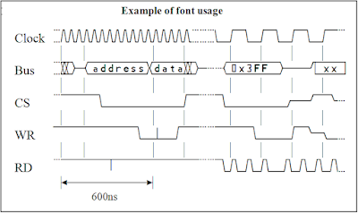
  • Timing Diagram Font - This software allows to generate timing diagrams in MS Word font. An example GIF generated using above tool is provided below(from the given link only)
Fig 3. Timing Diagram from Timing Diagram Font

I found above tools pretty interesting to play with and they save time while working.

I hope above tool will also help in your journey.

Let me know if you know of any other tool which is simpler to use than above. 

Till next post !!!

***Please note the images put in above figures are taken from the tool sites respectively. I dont have a copyright on above images.