Monday, 29 August 2016

Verification | System Verilog | Universal Verification Methodology - I

Over the last few months, I have been working on verification of SoCs using System Verilog/Universal Verification Methodology (or popularly known as SV/UVM in the VLSI Industry). I thought that I will create a list of sites, links to the important documents from various sources which I have used to develop my skill set in the said area. 

Also, I will try to list the interview questions which are highly useful and generally asked by most of the VLSI Companies hiring for SV/UVM/Verification skill set. 

One of my friends has done a very good job of compiling a library to learn about SV/UVM on his site Verification Guide . One of the best thing about this site is that you can compile the code and run it on EDA Playground, a free online tool provider for running simulation/synthesis and many other utilities. EDA Playground is now a part of Doulos.

Verification guide provides you with lots of examples and also to test these examples by making the changes to the code on EDA Playground.

Do let me know your feedback, if you found the examples to be useful.

Before I close on this article, one important remark I would like to make is that knowing the language alone does not close the case. Language is just a tool to solve a problem. It is the problem solving ability that matters. :)

Please do look out for this section as there are many articles coming up in this space(Along with generally asked interview questions)

Closing with the lines of  John Johnson, “First, solve the problem. Then, write the code.” 

Till next post!!!

Saturday, 27 August 2016

Free Timing Diagram Drawing Tools

In the VLSI industry, it is a requirement to come up with timing diagrams for the operations of circuits, blocks and IPs. It is also required at times about how the blocks interact with each other. This timing information is captured using waveform in the Design Specification docs and also in testplan many a times. In such a situation there is a requirement to draw the diagrams showing the relations ship between different signals and their alignment with the clock. 

Though you can get the job done using Microsoft Powerpoint/Microsoft Visio/Microsoft Excel, however, there are multiple online free tools available to make timing diagrams in the format we want(and also in lesser time than above and hence contributing to our productivity).

I am listing some of the tools which can be used(My personal favorite is WaveDrom. It even has a dedicated SNUG paper for it)

  • WaveDrom - It can be installed in your computers or can be run online to create timing diagrams. It creates timing diagram using simple textual inputs (basically a javascript).  Here's the link to SNUG paper on it. The link has a tutorial also and it is very easy to use.Below is the sample image generated from WaveDrom :

                                                                     Fig 1. Timing Diagram from WaveDrom
  • DrawTiming - It is also a very simple tool with a command line interface which allows you to write scripts(pretty intuitive). Below is a sample image from the tool site :

                                              Fig 2. Timing Diagram from DrawTiming

  • Timing Editor - It is another free waveform editor which can be used to create timing diagrams.
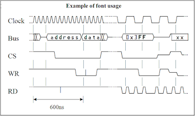
  • Timing Diagram Font - This software allows to generate timing diagrams in MS Word font. An example GIF generated using above tool is provided below(from the given link only)
Fig 3. Timing Diagram from Timing Diagram Font

I found above tools pretty interesting to play with and they save time while working.

I hope above tool will also help in your journey.

Let me know if you know of any other tool which is simpler to use than above. 

Till next post !!!

***Please note the images put in above figures are taken from the tool sites respectively. I dont have a copyright on above images.